Electrical wiring diagrams of a plc panel. The diagram should show incoming power feeding a receptacle.
Circuit breaker load centers for use on electrical systems are ul listed under file e 6294 panelboards and meet federal specifications w p 115c type 1 class 2 for use in government housing.

You can find out more Diagram below
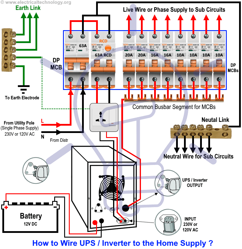
Circuit breaker panel wiring diagram pdf. They contain either a main breaker when used at the service entrance point or a main lug when used as a sub panel to add circuits to existing service. This 20 amp 120 volt breaker is a form of gfci that can be installed at the circuit source. In most panels the main breaker is a large 240 volt circuit breaker that is located at the top of the panel.
This kind of circuit is used for dishwashers whirlpool spas and other locations where water contact is likely. It provides the primary means for a homeowner to disconnect the power that comes from the feed provided by your electric utility company. This diagram illustrates wiring for a circuit breaker with a built in ground fault circuit interrupter or gfci.
Wiring a gfci circuit breaker. Service entrance panel sep the electrical panel breaker box fuse box load center or service entrance panel it is known by many names figure 4 has the job of distributing power throughout your home. This is done by removing the two square drive screws at the rear of the plastic moulding covering the panel.
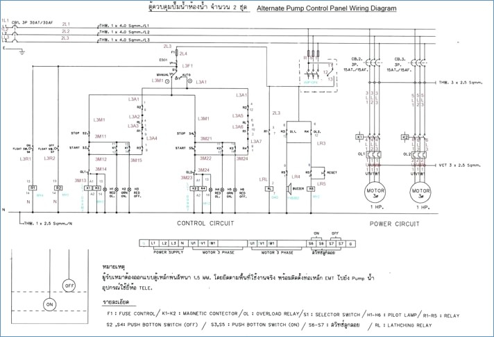
Basic wiring diagram have students produce a basic wiring diagram. 41 field circuit breaker 42 running circuit breaker 43 manual transfer or selector device 46 reverse phase or phase balance relay 47 phase sequence voltage relay 48 incomplete sequence relay 49 machine or transformer thermal relay 50 instantaneous overcurrent 51 ac time overcurrent relay 52 ac circuit breaker. The electrician now bends the two black service wires for easy installation to the main breaker.
Transformers to step down ac supply voltages to lower levels. The main breaker protects the main entire panel and can be used as a service disconnect. To refitreplace a label or to repositionreplace a circuit breaker the front cover of the bep panel must be removed.
It will control all the power entering the home and connects to both hot buss bars running down vertically through the panel. The electrical design for each machine must include at least the following components. In an industrial setting a plc is not simply plugged into a wall socket.
The branch circuit breakers and wiring required to distribute power to individual circuits. 5 installation panel mounting all bep panels require a 10mm inset on all external edges. Circuit drawings and wiring diagrams electrician 8 youth explore trades skills activity 2.
Johnson outboard wiring diagram pdf. Free wiring diagrams for johnson s and evinrude s many free wiring diagrams for johnson s and evinrude s many years and models johnson outboard wiring diagram pdf imageresizertool johnson outboard wiring diagram pdf to her with 1971 1989 johnson evinrude 1 25 thru 60 hp service manual pdf to her with wiring diagram for. The wiring diagram will show the circuit students will wire in wiring devices and wiring a wall section.


0 comments:
Post a Comment