If you only need two switches leave out both the 4 way switches. The diagrams on this page illustrate connecting multiple lights in 3 way and 4 way switch circuits.
Conventional 4 way switch wiring.
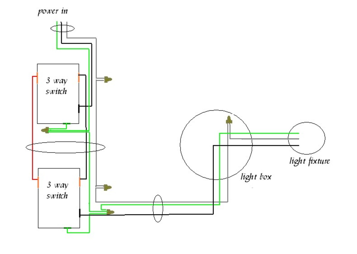
You can find out more Diagram below
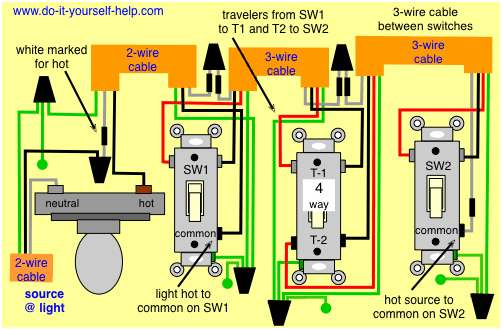
3 way and 4 way switch wiring diagram. The white wire of the cable going to the switch is attached to the black line in the fixture box using a wirenut. 4 way dimmer switch wiring diagram. This 4 way switch diagram 2 shows the power source starting at the fixture.
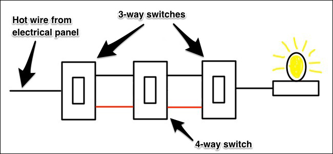
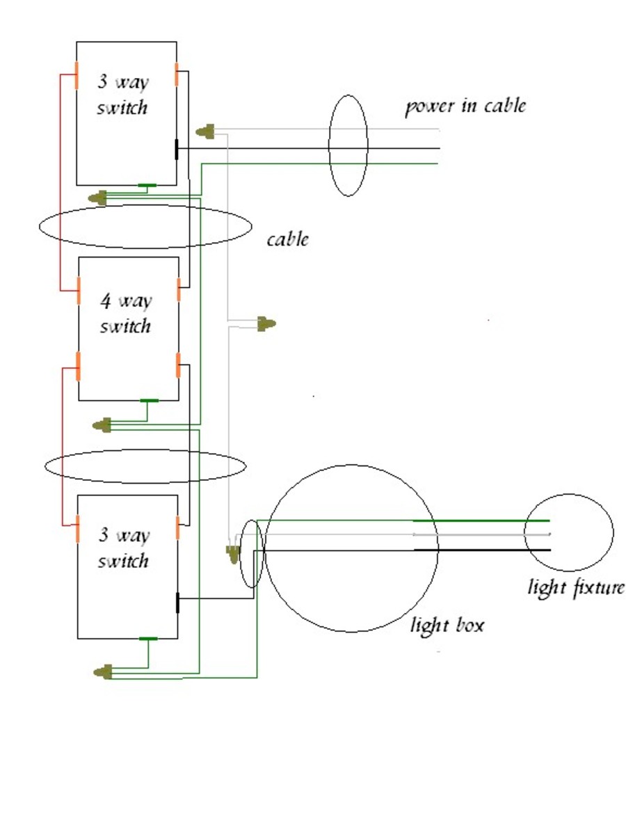
While the physical location of the 4 way switch may be anywhere the electrical location of the switch is always between the two 3 way switches. Here are another couple of variations of 3 and 4 way switch circuits. The travelers actually pass the electricity between the two 3 way switches as well as the 4 way switches shown in the 4 way switching wiring diagrams.
To make this circuit work a 3 way dimmer can be used in place of one or both of the standard 3 way switches. 3 way switch wiring diagram line to light fixtureline voltage enters the light fixture outlet box. You can also add as many 4 way switches as you like in place of any one shown in the circuits that follow.
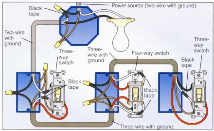
Three wire cable runs between all the switches and 2 wire cable runs to the light. I have a few of the most common ways in wiring a 4 way switch to help you with your basic home wiring projects. No longer allowed after 2011 nec if no neutral wire in switch boxes 3 way switch wiring diagram light fixture between switchesline voltage enters the first 3 way switch outlet box light fixture is located between switch boxesno longer allowed after 2011 nec if no neutral wire in switch boxes.
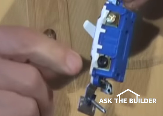
A 3 way switch has three screws plus the green grounding screw. 4 way switches have four terminals each with two pairs of travelers one set usually black and one set usually brass color. In the diagrams below the first switch 3 way common terminal connects to.
Wiring a 3 way switch with multiple lights. If additional 4 way switches are needed they will also go between the 3 way switches. Check below for more details about these circuits and some troubleshooting tips.
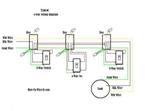
A 4 way switch wiring diagram is the clearest and easiest way to wire that pesky 4 way switch. This 4 way switch diagram 1 shows the power source starting at the left 3 way switch. A four switch configuration will have two 3 way switches one on each end and two 4 way switches in the middle.
All the 4 way switches are optional. The most important screw is the black one continuous hot and light feed wire goes on black screw traveler wires go on the brass screws 143 with ground or 123 with ground wire best to use between switches watch all videos below for. Here is an example of a light in the middle of the run.
To illustrate the wiring of these 3 way switches switch boxes and fixture boxes are not shown but are obviously required for every application. This is the wiring for a dimmer in a 4 way circuit. The two wiring diagrams above are of a 3 way switch setup and the same basic setup with a 4 way light switch added.



0 comments:
Post a Comment